- Research
- Open access
- Published:
Towards modular composition of agent-based voltage control concepts
Energy Informatics volume 2, Article number: 26 (2019)
Abstract
In the last years, diverse agent-based concepts for voltage control in distribution grids were presented in literature. All these approaches are developed manually. Up to now, no tailoring approach has been presented to adapt these concepts to different – likewise specific – grid situations. As the effectiveness of voltage control schemes is highly dependent on the specific grid situation, this can result in multiple problems with regard to performance, applicability and expandability of the proposed agent-based control. The ideal case would be a customizable agent system that is automatically tailored to the grid it shall be applied to, considering its specific characteristics. To address that complex task, this paper proposes an approach for the modular composition of voltage control agents by recombining existing concepts from literature to new fully functional agent systems. This approach makes the first move to an optimized and scenario-specific creation of agent-based control systems that are specifically designed and automatically tailored to a given power system.
Introduction
The increasing penetration of distribution grids with new actuators on both the generation and load side, like distributed generations (DGs), heat pumps and electric vehicles, results in temporally fluctuating voltage profiles (Pepermans et al. 2005; Bhattarai 2015). That may result in violations of the voltage boundaries and endangers voltage stability. In consequence, new real-time voltage control concepts are necessary to avoid expensive grid expansions (Seack et al. 2014).
The main option to perform voltage control is the usage of on-load tap-changing transformers (OLTCs), which regulate the voltage level of the whole underlying grid. Step voltage regulators (SVRs) are based on the same principle, but regulate the voltage level within a feeder (Kundur 1994). In contrast to OLTCs and SVRs, reactive power regulation allows to solve voltage problems in a local way. Available reactive power actuators are for example reactive compensating devices or inverter-based DGs. Thus, DGs not only induce voltage problems but also provide solutions to solve them (Morren et al. 2005). In distribution systems, also active power regulation plays an important role for voltage control, because of the higher R/X ratio of the system. But these measures often have major drawbacks. For example, load shedding is equivalent to a partly failure of energy supply, and curtailment of active power feed-in results in economic losses for the unit operators.
Making use of the distributed actuators in the distribution grids, diverse multi-agent control system (MACS) based concepts were proposed in literature to coordinate the available flexibilities for voltage control and to support conventional voltage control using utility-side voltage control and tap-changers (Antoniadou-Plytaria et al. 2017). Using information and communication technology (ICT) based multi-agent control, new concepts have been presented that allow for an adaptive and predictive voltage stabilization in dynamic grid topologies. The common approach to create a MACS for voltage control is to manually design an overall concept and to evaluate it in different grid scenarios. In distribution grids though, there is no typical or exemplary grid that can be used as a general benchmark (Deutsche Energie-Agentur (dena) 2012). When moving further from research to field application though, the evaluation of MACS has to be adapted step-wise to specific needs in the field (Nieße et al. 2013). Regarding multi-agent voltage control, the performance of a voltage stabilizing concept is relevant in all kinds of grids (especially regarding grid topology, generation and load situation, voltage stabilization flexibility), as well as the reflection of engineering overhead to adapt a generic approach to a specific grid situation. The following problems may arise when such a control concept is applied to grids it has not specifically been developed for:
-
Performance: A MACS that was derived from a general concept most probably cannot achieve the same performance as a MACS which was designed customized in a grid-specific way.
-
Applicability: The design process is mostly done based on various assumptions and simplifications, e.g. regarding grid topologies or load flexibility. For example, the MACS from (Wu et al. 2017) is designed for radial grids only. Consequently, these concepts are mostly only applicable to a limited share of tasks that meet the assumptions of the MACS designer.
-
Expandability: If an additional feature is to be implemented in an already self-contained and optimized MACS concept, either a complete re-design is necessary to avoid negative effects on the performance. This is highly relevant in distributed agent-based systems, as interactions of single agents may not be known during design time and undesired emergent behavior (negative emergence) may occur (Mogul 2006).
Consequently, the manual design of MACS concepts is not expedient for voltage control; algorithmic and more modular approaches should be developed. To realize an engineering approach, one option would be to automatically create a customized MACS for a given task, based on the grid it shall be applied to and identified metrics.
The long-term vision of the work presented here aims for the development of adaptive and learning agent-based voltage control systems that can be trained for the specific grid they shall be applied to. Such adaptive MACS would be capable of dynamically choosing from a set of behaviors depending on the (maybe even dynamic) grid scenario. The main benefit of these systems would be the reduced engineering effort that would be needed to realize new and highly tailored voltage control systems in the field, thus paving the way to both technically relevant and economically promising business models. The general procedure of such a design process including relevant exemplary properties is displayed in Fig. 1. To achieve that, multiple steps must be conducted:
-
1
Verify that it is feasible to compose a MACS for voltage control from different agent types and / or agents’ behaviors that were not designed to be compatible originally.
Fig. 1 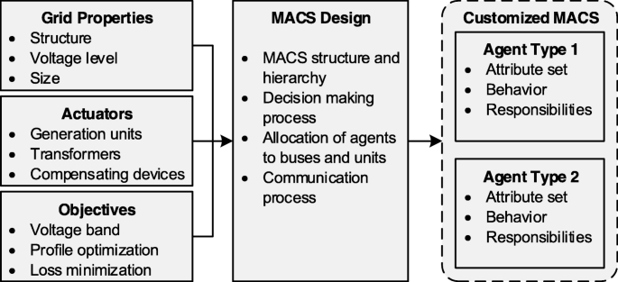
General procedure of MACS design, based on the properties and actuators of the considered grid and the aspired objectives (static view)
-
2
Automate and modularize the composition process of the agents and the MACS.
-
3
Setup a conflict resolution method regarding overlapping resource usage (e.g. different behaviors controlling tap-changers).
-
4
Integrate an automated design process in an optimization algorithm for an optimized and grid-based MACS creation.
-
5
Rebuild the system based on learning agents and identify an appropriate training concept (e.g. regarding frequency of re-training the agents) to reflect a dynamic grid topology.

In the work presented here, thefirst step is addressed: This paper proposes a concept of creating agents that combine traits of already existing MACS concepts by recombining them. This way it is possible to easily compose new agents by freely choosing from a large behavior set. The main contributions of this paper are:
-
1
An exemplary new MACS for voltage control is composed only by recombining traits of two basis multi-agent system (MAS) concepts from literature.
-
2
The feasibility of the approach is demonstrated by applying the composed MACS to test cases and by comparing its performance to the two basis concepts.
Agent-Based Voltage Control
There are numerous approaches and ideas to achieve distributed voltage control with MACS (Antoniadou-Plytaria et al. 2017). Wu et al. propose a hybrid hierarchical MACS that consists of an OLTC agent and multiple section agents (Wu et al. 2017). The central OLTC agent collects the voltage data from the whole grid and finds the optimal tap-position of the OLTC this way. Also, it requests the section agents to perform active or reactive power regulation under usage of their local actuators. Elmitwally, Elsaid, and Elgamal present a fully distributed approach where the single agents ask nearby agents for reactive power support or load shedding, if the voltage band is violated (Elmitwally et al. 2015). Elkhatib, El-Shatshat, and Salama mainly focus on the tap-changer of the OLTCs based on an estimation of the maximum and minimum network voltages (Elkhatib et al. 2011). The flexibility potential of DGs is deliberately neglected. In general, most of the concepts focus on reactive power regulation and the use of the OLTCs. In (Rohbogner et al. 2014), the agents also heavily rely on active power regulation, which is included by providing financial incentives to the agents. While all the previous concepts use the current state of the system as decision basis, (Nassaj and Shahrtash 2018) implement a predictive scheme that also takes into account the trend of the measured voltages to improve voltage regulation. In (Bahramipanah et al. 2016), the authors propose a concept that clusters the distribution grid into independently regulated areas and focus on distributed storage systems as actuators only, again assuming that DGs are not available for voltage control. In (Vaccaro and Zobaa 2013), the voltage control task is conducted under usage of the meta-heuristic simulated annealing technique which allows the consideration of arbitrary objective functions. The authors of (Bolognani et al. 2015) and (Kryonidis et al. 2019) describe voltage regulation as optimization problem aiming for active power loss minimization under subject to compliance with the voltage band as constraint. In (Manditereza and Bansal 2016), a completely different approach is chosen by using reactive power to nullify the voltage deviation induced by active power feed-in of DGs which makes conventional voltage control possible again.
Figure 2 classifies the presented approaches into different categories in a morphological box. The degree of shadiness indicates how many concepts fall in the respective variant of the named category. As categories included are the objective of the voltage control task, the actuators that are used, the considered constraints, the network topology it is applicable to, the allocation of the voltage control agents to the grid buses, and the first action that is performed for voltage control which reveals what the authors consider as preferred measure to perform voltage control. The compliance with the voltage band can be considered as constraint of an optimization, or as design objective depending if the task is seen as constraint satisfaction problem or optimization problem. Here, it is categorized as objective, because the authors consider compliance with the voltage band as the main objective of voltage control in general. The figure demonstrates that although all these concepts fall in the category of voltage control, the objectives pursued are sometimes completely different, e.g. optimization of the voltage profile or loss minimization. The same applies for the execution of the regulation or the considered grid types. That reveals a great dissent in literature regarding voltage control which results in the great diversity of approaches. That in turn leads to the problematic issue that all these concepts are only applicable to small subsets of use cases, which was already stated in the previous section.

Classification of MACS-based voltage control concepts from literature regarding their design decisions. Including (Wu et al. 2017; Elmitwally et al. 2015; Elkhatib et al. 2011; Rohbogner et al. 2014; Nassaj and Shahrtash 2018; Bahramipanah et al. 2016; Vaccaro and Zobaa 2013; Bolognani et al. 2015; Kryonidis et al. 2019; Manditereza and Bansal 2016)
Composition of Different Voltage Control Concepts
Two cooperative MACS based voltage control concepts were chosen for recombination. The concept from (Wu et al. 2017) is a hierarchical MACS for radial distribution grids that aims for compliance with the voltage constraints and an additional optimization of the voltage profile. It is called HRCO in the following, based on its main characteristics (Hierarchical, Radial grids, voltage Constraints, and Optimization). The second concept, derived from (Elmitwally et al. 2015), is a fully distributed MACS that is applicable to all grid types and focuses only on the compliance with the voltage boundaries. It is called DAC here (Distributed, All grid types, voltage Constraints). These explicit concepts were chosen for two main reasons: Both concepts are well and comprehensible documented, and therefore easily implementable. Also, as can be seen by their main characteristics, they represent two completely different approaches to the task of agent-based voltage control. That supports the main point of this paper to recombine MACS that were not designed to be used together and show completely different approaches. Both concepts were implemented by their descriptions from literature.Footnote 1 In the following, the both procedures are summarized in a brief and simplified way. For further and more detailed information it is referred to the original papers (Wu et al. 2017) and (Elmitwally et al. 2015).
HRCO Concept
The HRCO is a hierarchical system consisting of two hierarchy levels which are represented by two agent types: the superordinate OLTC agent which is responsible for the OLTC and the whole underlying grid, and the subordinate FCS agents that are responsible for a group of buses within a feeder control section (FCS). The agents perform voltage regulation to not only ensure constraint satisfaction of the voltage band, but also to perform an optimization of the voltage profile. The concept is applicable to radial grids only.
The FCS agents measure the local voltage level at their section and forward these data to the central OLTC agent continuously. Apart from that, they do not perform actions autonomously, but wait for requests from their superordinate OLTC agent. Two kinds of requests are possible: cooperative active power regulation and reactive power regulation (CQ). When a FCS agent receives a request for reactive power regulation, it coordinates cooperative solution search within its feeder with the objective to minimize the sum of the quadratic deviations from nominal voltage in the feeder. That optimization is performed on the basis of the reactive power sensitivity X Si,j which describes the linearized voltage change at bus i that results from a reactive power feed-in change at bus j (Eremia and Shahidehpour 2013).
The same general procedure is used for active power regulation, but this time the objective function is the minimization of the active power curtailment under compliance with the voltage band.
The superordinate OLTC agent collects the voltage data from the FCS agents and uses them to determine the overall state of the grid. Based on that, it performs tap-changing, requests active or reactive power regulation from the FCS agents, or combinations of all three.
DAC Concept
The DAC concept is based on a fully distributed MACS which focuses on reactive power regulation. In contrast to the HRCO concept, an optimization of the voltage profile is not carried out. The agents are able to include line congestion in their actions, but that is neglected here to focus on voltage control only. In the original paper (Elmitwally et al. 2015), it is distinguished between three types of voltage control agents, but for the sake of simplicity only their general behavior is summarized here.
One agent is responsible for a single bus within the grid. If that agent detects a voltage violation at its bus, it tries to solve the problem locally by gradually adjusting the reactive power feed-in of the local generator.Footnote 2 If local reactive power adjustment is not sufficient or not possible (e.g. no actuator), the concerned agent requests reactive power support from other agents. That is scheduled based on a reactive power sensitivity ranking. If the asked agent accepts the request, it will perform gradual reactive power regulation at its own DG until no more regulation is possible or until it receives a message that the regulation was successful. If the request gets rejected, the concerned agent will ask the next agent and so on. If all agents reject reactive power support, the same procedure is rerun by requesting load shedding. That is done only in undervoltage situations.
Recombination of the Concepts
To address step 1 (Verify that different agent-based voltage control concepts can be recombined, see Introduction), a case study has been performed. Goal of this case study was to show that a recombination of voltage control concepts is possible and can show meaningful behavior in specific grid situations. The two voltage control concepts HRCO and DAC show some obvious weaknesses which result from the manual MACS creation approach which was described before. For example, the HRCO concept is only applicable to radial grids which makes it generally impossible to use for other grid types. Also it relies mainly on the central OLTC agent. If that agent malfunctions in any way (hardware/software), the whole MACS fails, because the FCS agents are not able to perform control actions proactively. The concept thus shows the single-point-of-failure weakness. The DAC concept on the other hand lacks a possibility to curtail active power feed-in of the generators to clear overvoltage situations. Also, the agents stop voltage regulation as soon as the voltage band is recovered. That results in voltages that are close to the permitted boundaries which is far from the optimal state of the system and results in fast re-occurrence of voltage violations, if the system state changes again. Despite these weaknesses, it is important to state that both concepts provide efficient and carefully designed approaches for voltage control, which lay a basis to create more advanced voltage control agents.
For the reasons given, this paper proposes an approach to create new MACS for voltage control by recombination of existing approaches. In the following, the recombination approach is presented by an exemplary and manual merging of the DAC and HRCO concepts as a proof-of-concept. Beforehand, we discuss what difficulties need to be overcome in the process. In Table 1, the two basis concepts are classified with regard to the categories of the morphological box in Fig. 2 which highlights the differences between both approaches regarding design objective, grid topology, agent allocation and main voltage control action.
These explicit differences in the basis MACS design hint that multiple problems and difficulties have to be overcome during the manual recombination process which follows. A design decision has to be made what the explicit objective of the overall agent system is. Only the compliance with the voltage band or an optimized voltage profile? An additional optimization makes the agents more powerful, but also may result in coordination problem, because the complexity of the problem increases. The same applies for the decision if the MACS is applicable to all kinds of grids or restricted to radial grids only. Further, it must be chosen, whether one agent is responsible for a single bus, a section of buses, or even a combination of both. Another design decision is the coordination of the diverse actions that the agents are able to perform. In a given situation, should the agents act like a DAC agent or a HRCO agent? And based on what conditions is that decision made by the agents? That is especially relevant, if both basis concepts would result in conflicting actions, for example, if they regulate the same unit in different ways.
In the presented re-combination of the concepts, the general MACS hierarchy structure of HRCO is maintained: one central OLTC agents that controls the transformer and oversees all other agents, and multiple subordinate bus agents that control a single bus in the grid. It was chosen to give one agent the responsibility for a single bus, because that is equivalent to a feeder control section consisting of only one bus. Therefore, this agent allocation is compatible to both basis concepts.
If a bus agent detects a violation of the voltage boundaries, it tries to solve the problem locally or asks for reactive power support, exactly as in the DAC concept. Compared to the HRCO approach, that ensures fast and autonomous reaction of the agent, because no trigger from the OLTC agent is necessary anymore. That also makes a failure of the central OLTC agent less problematic. Additionally, the reactive power regulation is performed as close to the violation as possible, which results in less power losses in the grid (Kryonidis et al. 2019). Nevertheless, the bus agents still send their measured voltage values to the OLTC agent, which allows it to find the optimal tap-position of the transformer, as in the HRCO concept. That is important because tap-changing is an action that affects the whole grid and should be performed on the basis of as much data as possible. The knowledge of the grid voltages also enables the OLTC agent to perceive the successful clearing of the voltage violations which is used as a trigger to start cooperative reactive power regulation as in the HRCO concept. Consequently, no overlapping of HRCO’s and DAC’s reactive power regulation takes place, but still an optimization of the voltage profile can be performed after violations are cleared successfully. This way, a clear line is drawn in which cases the DAC actions are executed and in which cases the HRCO actions instead. To obviate situations where reactive power regulation and tap-changing are not sufficient to clear overvoltage situations, cooperative active power regulation as in the HRCO concept is performed in that situation. The same applies for the load shedding of the DAC concept in undervoltage situations.
This way, a new MACS concept for voltage control could be created with minimal newly written code just by re-composition of already implemented agent behaviors. To overcome potential conflicts in the agents’ behavior, multiple design decisions regarding the combination had to be made. In future works, a concept must be developed how these design and coordination decisions can be made automatically to overcome the manual design of agent control systems (see step 2 and 3 of the long-term vision).
Simulation Environment
The software-based recombination of MACS in voltage control applications is only possible, because both concepts are implemented in the same simulation environment. That joint environment is also necessary to evaluate and compare the performance of multiple MACS based voltage control concepts under equal conditions. The simulation environment created for that task consists of three main components: a simulation of the grid and its operating unit models, an environment for the MACS that controls the grid, and an event manager which is responsible to induce voltage violations by triggering pre-defined sets of events. The whole environment is implemented in pure python. For the network simulation and power flow calculation, the pandapowerFootnote 3 module is utilized (Thurner et al. 2018). As a MACS framework, aiomasFootnote 4 was chosen. The whole environment is built highly modular with the co-simulation framework mosaikFootnote 5 which is used to handle and coordinate the data exchange between the encapsulated simulators and tie them together (Rohjans et al. 2013). That modular build also allows easy exchange of different MACS implementations. Figure 3 shows the structure of the created simulation environment in a simplified way.

Structure of the simulation environment with data flows between and within simulators
At the beginning of each step, the units perform the commands given by the MACS and are updated in accordance to the triggered events of the respective time step which are transmitted by the event manager. Afterwards, the power system gets updated with the new state of the units and a power flow simulation is carried out. The results of the calculation are used to re-update the units, for example voltage data to the measurement units. The new state of the units, including the voltage data of the grid, is sent to the agents which then decide certain actions considering their new knowledge and possibly exchanged messages among each other. Finally, the actions to be performed are sent to the units, which starts the next step of the simulation. For the work presented here, a simulation step size of one second was chosen.
Results
The simulation environment is used to apply the implemented MACS concepts to multiple test cases. This way, the operational capability of the recombined MACS can be demonstrated and compared to the original MACS concepts HRCO and DAC.
In the context of this work, a test case is the combination of a given power grid and a set of events that would without further control actions result in one or multiple violations of the voltage band. That allows to evaluate the MACS with regard to their performance in preventing or clearing these voltage violations. The 25-bus low voltage (LV) grid which is utilized for the simulations is visualized in Fig. 4.

rural_1: Small radial LV grid with 25 buses and 5 DGs, adapted from (Lindner et al. 2016)
It was introduced in (Lindner et al. 2016) especially for the investigation of voltage problems and is included in the pandapower packageFootnote 6. For simplification purposes, the muff buses are not displayed. To make proper voltage regulation possible, it is assumed that the transformer is tap-changable with a step size of 2.5% and that the DGs are able to freely choose a reactive power feed-in in the range of [ −35 kvar; + 35 kvar].
In this paper, overall four test cases are simulated to compare the recombined MACS to its basis concepts. Table 2 provides short descriptions of the test cases.
Test Case 1
In test case 1, an instantaneous voltage increase in feeder 1 is induced at simulation step 10. That is done by increasing the active power feed-in of the respective DGs by the factor of 2.5, and by decreasing the active and reactive power demand of the loads within the feeder to zero.
The three sub-plots in Fig. 5 show the resulting voltage courses of applying the HRCO and the DAC concept, as well as the recombination of both, to test case 1. To assess if the voltage band is violated, only the overall maximum and minimum voltages of the grid are necessary. These are plotted in red and blue respectively. The voltage band, which was chosen as the range [0.95 pu; 1.05 pu], is delimited by the black horizontal lines.

Test case 1, resulting voltage courses when applying: a DAC, b HRCO, c Recombination: DAC+HRCO
DAC
When the violation is induced at simulation step 10, the DAC agents detect the local voltage increase at their buses and perform gradual reactive power regulation within the feeder to decrease the local voltage level. That leads to a fast and simple clearing of the violation at simulation step 18.
HRCO
The HRCO MACS reacts in a different way to the same situation. At the beginning of the simulation, no violation is active, which is why the agents perform an optimization of the voltage profile under the usage of reactive power. That results in a smaller magnitude of the actual violation in step 10, which is a great advantage of this concept. As soon as the violation is induced, the central OLTC detects that the general voltage level of the grid is too high and performs a tap-change of the OLTC in step 26Footnote 7, which clears the violation. Finally, the voltage profile is optimized again.
DAC+HRCO
The third sub-plot shows the voltage course when the presented recombination of both concepts is utilized. It is clear that the voltage course shows traits of both basis concepts. At the beginning, optimizations of the voltage profile are performed, as in the HRCO concept. When the violation is induced at step 10, the agents act locally by adjusting reactive power feed-in, as in the DAC concept, which results in the same fast and simple violation clearing. Finally, when the violation is cleared, the voltage profile is optimized again which results in a similar end result as in the case of the HRCO MACS.
Test Case 2
In test case 2, a voltage level decrease in the whole system is induced by increasing all loads by a factor of 3.0 and reducing active power feed-in of all DGs to zero. Additionally, the two DGs in feeder 0 are set out of service to examine the behavior of the agents in situations with less flexibility. The resulting voltage courses are shown in Fig. 6.

Test case 2, resulting voltage courses when applying: a DAC, b HRCO, c Recombination: DAC+HRCO
DAC The DAC agents try to clear the violations with reactive power feed-in increasing. But in this case, the maximum feed-in is not sufficient to clear the violations completely. Because of that, the agents go to a load shedding state which results not only in a slow voltage increase but also undermines the main objective of voltage control, reliable energy supply. Overall, 110 steps are required to clear the violation which cannot be shown completely here. That demonstrates that the DAC concept relies mainly on reactive power and requires large reactive power leeway to succeed.
HRCO The HRCO agents face the same problem of narrow reactive power operational bounds, which can be seen at simulation step 13 in sub-plot B). But the OLTC agent is able to perform tap-changing when no further reactive power increase is possible, because the FCS agents inform the OLTC agent about the generally too low voltage level within the grid. In conclusion, the HRCO concept relies not only on one approach but provides multiple possibilities to solve a given voltage problem.
DAC+HRCO The third sub-plot shows the voltage course for the recombined concept. Generally, the voltage course equals the result from the HRCO concept. First, reactive power regulation is performed. But when that reaches its limits, tap-changing is used to clear the voltage violation. That demonstrates that the flexibility from the HRCO concept was adopted successfully.
Test Case 3
Figure 7 shows the results for test case 3. Here, it is investigated how the MACS react to situations where the voltage band in the superordinate medium voltage (MV) grid is violated. To induce this situation, the voltage of the slack bus 0 is set from 1.0 pu to 0.92 pu at simulation step 10. Additionally, to simulate a subsequent clearing of that violation, the slack voltage is set back to 1.0 pu at step 45.

Test case 3, resulting voltage courses when applying: a DAC, b HRCO, c Recombination: DAC+HRCO
DAC Again, the DAC agents perform reactive power regulation until the violations are cleared. The local reactive power adjustment is finished after only few simulation steps in both cases. Also, the additional reactive power feed-in in the time-frame between step 10 and step 45 results in a reactive power flow to the superordinate MV grid which helps to stabilize the voltage level there.
HRCO In contrast to that, the HRCO MACS mainly performs tap-changing to regulate the voltage level. On the one hand, the violations occur in a grid-wide scale which makes tap-changing generally reasonable. On the other hand, decreasing of the OLTC’s tap-position increases its admittance and therefore worsens the voltage violation in the MV grid. Additionally, the repeated tap-changing results in strong voltage fluctuations and unrest in the whole LV grid.
DAC+HRCO The recombined MACS shows traits of both basis concepts. Generally, the voltage violations get cleared under usage of reactive power regulation which maintains the positive effect for the concerned MV grid. Additionally, an optimization of the voltage profile is performed after violation clearing. To do so, tap-changing and reactive power regulation are utilized, which would not be possible with the DAC concept alone. Overall, the great advantage of the DAC concept was adopted successfully, while the negative as well as the positive sides of the HRCO MACS were adopted, too.
Test Case 4
In test case 4, a double violation of both the upper and lower voltage boundary is investigated, which is kind of a worst-case of a voltage violation problem. To induce the upper boundary violation, all loads are decreased to zero in feeder 0, and the active power feed-in of the respective DGs is increased by a factor of 3.6. In feeder 1, the loads’ active and reactive power demand is increased by a factor of 3.5 and the active power feed-in of the DGs is reduced to zero to violate the lower voltage boundary locally. Figure 8 shows the resulting voltage courses.

Test case 4, resulting voltage courses when applying: a DAC, b HRCO, c Recombination: DAC+HRCO
DACThe DAC agents perform reactive power feed-in decreasing in feeder 0 and increasing in feeder 1 to clear both violations concurrently. That works well until the respective reactive power boundaries are reached in all DGs of both feeders. With the given reactive power potential it is possible to clear the violations in only one of the feeders, but not both at the same time. That happens in step 16 when the upper voltage boundary is no longer violated in feeder 0. But the two feeders are not completely decoupled and the ongoing regulation in feeder 1 results in another voltage violation in feeder 0. As soon as the agents in one feeder succeed in clearing the local violations in their feeder, they receive help requests by agents of the respective other feeder to perform voltage regulations. That in turn clears the violation in that feeder, but also induces new violations at the local buses. In consequence, that results in the oscillating behavior of the voltage course which can be seen from step 20 onward. It was described before that the agents are also able to perform load shedding, if reactive power regulation is not sufficient. Although active power regulation would be useful here to clear the undervoltage violations in feeder 1, no load shedding is performed, because the agents always find another agent that provides reactive power support. This way, the agents never recognize that reactive power regulation is not a sufficient solution.
HRCOThe HRCO agents also increase reactive power input at feeder 1. At the same time, the agents in feeder 0 curtail the local active power feed-in. In sum, the general voltage level is increased. Because of that, the OLTC agent performs a tap-change in step 28 to lower the voltage level. By some additional active power curtailment, both violations get cleared in simulation step 31 which starts the optimization process with reactive power regulation. The agents in feeder 0 increase reactive power demand and lower the voltage level this way, which induces another violation of the lower boundary in feeder 1. That in turn results in a tap-change in step 48, because the general voltage level is too low. Finally, the active power feed-in of the DGs is increased again as far as possible without inducing another voltage violation.
DAC+HRCO The recombination concept uses traits of both concepts to clear the violations. First, the usual pre-violation optimization of HRCO is performed. Second, when the violations are induced, the agents locally perform reactive power regulation adopted from the DAC concept as far as possible. Additionally, the central OLTC agent is still able to request active power curtailment of the DGs to support the reactive power regulation in feeder 0, which is not sufficient alone, as seen in sub-plot A). The cooperative active power regulation was adopted from the HRCO concept again. Altogether, that results in successful clearing of all voltage violations within the grid from step 22 onwards. Also, it shows that the up- and downward tap-changing of the HRCO is not necessary to achieve the same end result, which indicates problems regarding the coordination of the actions in the HRCO concept.
Discussion
The two basis concepts from literature and the recombination of them both were applied to overall four test cases which allows an analysis and comparison of the results. The simulations confirm that both the HRCO and DAC concept show some advantages as well as disadvantages regarding the voltage control process.
The DAC concept provides an easy, fast and local way to perform reactive power regulations in case of voltage violations. But the agents face problems, when reactive power regulation alone is not sufficient, as seen in test cases 2 and 4. Also, no subsequent optimization of the grid’s voltage profile is included. The HRCO concept is much more flexible and powerful, utilizing tap-changing as well as active and reactive power regulation on a regular basis. But the tap-changing is comparatively slow compared to reactive power regulation and is used not only for global voltage problems but also for local violations of the voltage band, as seen in test case 1, which can be considered as problematic. Test case 3 demonstrated that extensive usage of the tap-changer could have negative consequences for the voltage situation in the superordinate grid. In addition, case 4 showed that the coordination of the three regulation processes may cause problems in some cases.
While both basis concepts failed in at least one of the test cases. The combination of both concepts resulted in a MACS that was able to solve all four voltage violation situations with overall better results than the basis concepts. As a simple performance measure, Table 3 shows the total number of simulation steps with at least one violation of the voltage band for all test cases and MACS concepts respectively. The performance measure confirms the qualitative evaluation. In each test case, the composed MACS achieves either about the same result as the respective superior basis concept or better results than both of them. That demonstrates that not only a recombination is possible but also that the composition can be superior to the basis concepts, if their specific strengths are combined in a way that they complement each other.
For the simulations, the test cases were created arbitrarily only to demonstrate the approach in principle. Applied to other test cases, the recombined MACS will most probably show weaknesses and failures, too. But the simulations successfully showed that it is possible to recombine existing behaviors from different MACS to fully functional and effective new routines, although the basis concepts were designed completely separately and had only few similarities. The DAC concept is fully distributed, while the HRCO is a hierarchical concept. The FCS agents from the HRCO concept were designed to oversee sections, the DAC actions are responsible for single buses, and so on. In conclusion, it is possible to re-design new agents or full multi-agent control systems in an easy and modular way. That in turn lays the basis for an algorithmic and demand-based creation of MACS for a given grid.
On the way there, diverse problems may arise and have to be overcome. In this work, the combination of the basis concepts was performed manually and multiple problems were discovered in the process. For example conflicting agent allocations or contradictory unit control triggers (see Recombination). Until now, there is no method how to overcome these conflicts automatically. There is even a possibility of conflicts that cannot be solved without serious second effects and drawbacks.
For the simulations in this work, only exemplary test cases were made. This way, a proof-of-concept is possible, but no general statements about the performance of a MACS. However, these are necessary not only to investigate applicability to realistic long-term scenarios but also to demonstrate advantages and disadvantages compared to conventionally designed agent systems.
Conclusion and Outlook
The state-of-the-art manual design of MACS results in shortcomings regarding the performance, applicability and expandability of the resulting MACS. To address that problem, this paper presents the first step to a new method of automatically creating MACS for voltage control by recombining traits of existing MACS concepts. A simulation environment for the implementation of voltage control concepts was set up, and two recently presented agent-based voltage control concepts from literature were implemented using that environment successfully. To demonstrate the recombination approach of this work, traits of both concepts were manually recombined to form a new MACS that is able to use features of both concepts for the voltage control task. Finally, all three agent systems were applied to overall four test cases in which voltage control actions were necessary to clear emerging violations of the voltage band. The analysis of the simulation results demonstrated that the recombination not only resulted in a fully functional MACS, but also that the new MACS achieved the best overall results regarding the four exemplary test cases. This way, we could show that it is feasible to compose a MACS for voltage control from different agent types and / or agents’ behaviors that were not designed to be compatible originally. Thus we addressed step 1 regarding the long-term vision of adaptive and learning agent-based voltage control systems as discussed in the introduction. That approach allows to create more complex and powerful agent routines and also provides the possibility for automation, customization, and optimization of the design process with a reduced engineering overhead as needed for field applications.
In (Van Berkel et al. 2012) and (Luke and Spector 1996), genetic programming was used to automatically find MACS algorithms for a given task and even for the single agents individually. In the process, a set of primitive functions was recombined to find optimal combinations. Alternatively, learning agents can be created that have access to all kinds of implemented behaviors and are able to learn which of them to use in a given situation. To achieve that, a large quantity of implemented primitive functions is necessary to create more versatile agents that are able to recognize and solve all kinds of voltage control problems. That is only possible, if the functions are implemented in a defined and consistent way to make them exchangeable, expandable and composable. The next steps with regard to the long-term vision will be the automatic handling of the composition process and the development of a conflict resolution method for overlapping resource usage. In future works, it is also necessary to simulate more complex and close to reality test cases in order make more general statements about MACS performances possible, instead of only exemplary cases.
Notes
In case of doubt, the authors of the relevant publications have been contacted for clarification.
In the original concept Uref of the generator’s automatic voltage regulator (AVR) gets adjusted. To make it applicable to generators without AVR and comparable to the HRCO concept, the generator model is modified to a PQ-element. The required reactive power adjustment is calculated from the desired voltage change as \(\Delta Q_{i} = \frac {\Delta U_{\tiny {\text {ref}},i}}{X\!S_{i,i}}\), under usage of the local reactive power sensitivity.
https://pandapower.readthedocs.io/en/latest/, last visit: 2019-06-27.
https://aiomas.readthedocs.io/en/latest/, last visit: 2019-06-27.
https://mosaik.readthedocs.io/en/latest/, last visit: 2019-06-27.
https: //pandapower.readthedocs.io/en/v1.6.0/networks/synthetic_voltage_control_lv_networks.html, pandapower version: 1.6.0, last visit: 2019-06-27.
A time delay of 15 s for an initial tap-change, and 5 s for all directly following tap-changes is chosen for this work, based on (Elmitwally et al. 2015).
References
Antoniadou-Plytaria, KE, Kouveliotis-Lysikatos IN, Georgilakis PS, Hatziargyriou ND (2017) Distributed and Decentralized Voltage Control of Smart Distribution Networks: Models, Methods, and Future Research. IEEE Trans Smart Grid 8(6):2999–3008.
Bahramipanah, M, Cherkaoui R, Paolone M (2016) Decentralized voltage control of clustered active distribution network by means of energy storage systems. Electr Power Syst Res 136:370–382.
Bhattarai, B (2015) Intelligent Control and Operation of Distribution System. PhD thesis. Department of Energy Technology, Aalborg University, Aalborg.
Bolognani, S, Carli R, Cavraro G, Zampieri S (2015) Distributed Reactive Power Feedback Control for Voltage Regulation and Loss Minimization. IEEE Trans Autom Control 60(4):966–981.
Deutsche Energie-Agentur (dena) (2012) Ausbau- und Innovationsbedarf der Stromverteilnetze in Deutschland bis 2030. Deutsche Energie-Agentur GmbH (dena), Berlin.
Elkhatib, ME, El-Shatshat R, Salama MMA (2011) Novel Coordinated Voltage Control for Smart Distribution Networks With DG. IEEE Trans Smart Grid 2(4):598–605.
Elmitwally, A, Elsaid M, Elgamal M (2015) Novel Multiagent-Based Scheme for Voltage Control Coordination in Smart Grids. J Energy Eng 141(3):04014025.
Eremia, M, Shahidehpour M (2013) Handbook of Electrical Power System Dynamics. John Wiley & Sons, Inc, Hoboken.
Kryonidis, GC, Demoulias CS, Papagiannis GK (2019) A new voltage control scheme for active medium-voltage (MV) networks. Electr Power Syst Res 169:53–64.
Kundur, P (1994) Power System Stability and Control. McGraw-Hill, Inc., New-York.
Lindner, M, Aigner C, Witzmann R, Wirtz F, Berber I, Gödde M, Frings R (2016) Aktuelle Musternetze zur Untersuchung von Spannungsproblemen in der Niederspannung. 14. Symposium Energieinnovation Graz, Graz.
Luke, S, Spector L (1996) Evolving teamwork and coordination with genetic programming In: Proceedings of the 1st Annual Conference on Genetic and Evolutionary Computation, 150–156.. MIT Press, Cambridge.
Manditereza, PT, Bansal RC (2016) Multi-Agent Based Distributed Voltage Control Algorithm for Smart Grid Applications. Electr Power Components Syst 44(20):2352–2363.
Mogul, J (2006) Emergent (mis) behavior vs. complex software systems, vol. 40. SIGOPS Oper. Syst. Rev.ACM, New York.
Morren, J, De Haan SWH, Ferreira JA (2005) Contribution of DG units to voltage control: Active and reactive power limitations In: 2005 IEEE Russia Power Tech, PowerTech.. IEEE.
Nassaj, A, Shahrtash SM (2018) A predictive agent-based scheme for post-disturbance voltage control. Int J Electr Power Energy Syst 98:189–198.
Nieße, A, Tröschel M, Sonnenschein M (2013) Designing Dependable and Sustainable Smart Grids - How to Apply Algorithm Engineering to Distributed Control in Power Systems. Environ Model Softw 56:37–51.
Pepermans, G, Driesen J, Haeseldonckx D, Belmans R, D’haeseleer W (2005) Distributed generation: definition, benefits and issues. Energy Policy 33(6):787–798.
Rohbogner, G, Fey S, Benoit P, Wittwer C, Christ A (2014) Design of a Multiagent-Based Voltage Control System in Peer-to-Peer Networks for Smart Grids. Energy Technol 2(1):107–120.
Rohjans, S, Lehnhoff S, Schütte S, Scherfke S, Hussain S (2013) mosaik - A modular platform for the evaluation of agent-based Smart Grid control In: IEEE PES ISGT Europe 2013, 1–5.. IEEE.
Seack, A, Kays J, Rehtanz C (2014) Time series based distribution grid planning approach with decentralised voltage regulation In: Proceedings - 2014 Power Systems Computation Conference, PSCC 2014.. IEEE.
Thurner, L, Scheidler A, Schäfer F, Menke J, Dollichon J, Meier F, Meinecke S, Braun M (2018) pandapower — An Open-Source Python Tool for Convenient Modeling, Analysis, and Optimization of Electric Power Systems. IEEE Trans Power Syst 33(6):6510–6521.
Vaccaro, A, Zobaa AF (2013) Voltage regulation in active networks by distributed and cooperative meta-heuristic optimizers. Electr Power Syst Res 99:9–17.
Van Berkel, S, Turi D, Pruteanu A, Dulman S (2012) Automatic Discovery of Algorithms for Multi-Agent Systems In: GECCO’12 - Proceedings of the 14th International Conference on Genetic and Evolutionary Computation Companion, 337–344.. ACM, New York.
Wu, H, Huang C, Ding M, Zhao B, Li P (2017) Distributed cooperative voltage control based on curve-fitting in active distribution networks. J Mod Power Syst Clean Energy 5(5):777–786.
Acknowledgements
We thank Martin Tröschel for proofreading and his kind feedback.
About this supplement
This article has been published as part of Energy Informatics Volume 2 Supplement 1, 2019: Proceedings of the 8th DACH+ Conference on Energy Informatics. The full contents of the supplement are available online at https://energyinformatics.springeropen.com/articles/supplements/volume-2-supplement-1.
Funding
No funding was received for this work. Publication of this supplement was funded by Austrian Federal Ministry for Transport, Innovation and Technology.
Availability of data and materials
The program code of the simulation environment will be published in a future step with a further publication.
Author information
Authors and Affiliations
Contributions
TW created the simulation environment, implemented both basis concepts, performed the recombination and the simulations. He also wrote most parts of this contribution. The basic idea of the work presented here originates from AN who also accompanied and supported the whole process as supervisor. She significantly contributed to the paper at hand. Both authors read and approved the final manuscript.
Corresponding author
Ethics declarations
Publisher’s Note
Springer Nature remains neutral with regard to jurisdictional claims in published maps and institutional affiliations.
Competing interests
The authors declare that they have no competing interests.
Rights and permissions
Open Access This article is distributed under the terms of the Creative Commons Attribution 4.0 International License(http://creativecommons.org/licenses/by/4.0/), which permits unrestricted use, distribution, and reproduction in any medium, provided you give appropriate credit to the original author(s) and the source, provide a link to the Creative Commons license, and indicate if changes were made.
About this article

Cite this article
Wolgast, T., Nieße, A. Towards modular composition of agent-based voltage control concepts. Energy Inform 2 (Suppl 1), 26 (2019). https://doi.org/10.1186/s42162-019-0079-x
Published:
DOI: https://doi.org/10.1186/s42162-019-0079-x